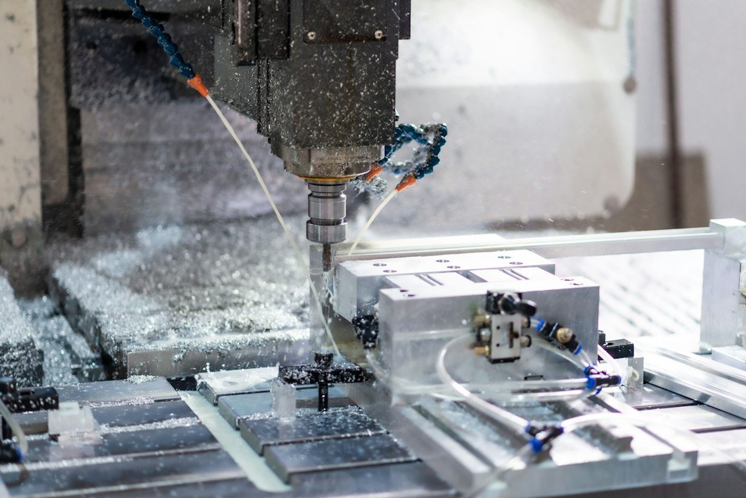
Good CNC design is not simply about making a CAD model that can be manufactured somehow. A better approach is to design the component so the machine tool can reach the features, use sensible cutters, hold the work securely, inspect the important dimensions and complete the part with as few setups as practical. This guide explains a CNC milling design workflow for mechanical engineers.
Start with the manufacturing process
Before adding small features to a model, identify the likely machine process. A three-axis vertical machining centre can machine many prismatic parts, but it has different access limitations from a four- or five-axis machine. The number of setups also affects cost and accuracy.
A designer should therefore ask: Can the part be clamped? Can the cutter reach the feature? Is there enough clearance for the tool holder? Can the important surfaces be referenced from a sensible datum? Can inspection equipment reach the critical dimensions?
Tool access is a design constraint
A pocket that looks easy in CAD may be difficult when a real cutter and holder are inserted. Deep narrow pockets may require long tools, and long tools are more prone to deflection and vibration. If the pocket does not require a sharp internal corner, adding an internal radius can make the feature much easier to machine.
For example, a rectangular pocket with perfectly sharp internal corners generally requires a special tool strategy if the corners must truly be sharp. A conventional end mill leaves an internal radius approximately related to its cutter diameter. Designing the corner radius intentionally is usually more practical.
Choose hole sizes intelligently
Holes are among the most common CNC features, but not every hole should be given an arbitrary diameter. Standard drill sizes can reduce tool changes and cost. If a hole only needs to pass a bolt, use a suitable clearance-hole size rather than unnecessarily specifying a precision bore.
When a close fit is actually required, define the functional requirement clearly and select an appropriate process such as drilling, reaming or boring. Do not apply a tight diameter tolerance simply because the CAD system allows it.
Blind holes and chip evacuation
Deep blind holes require attention to drill depth, chip evacuation and tool geometry. A designer should distinguish between the nominal hole depth and the actual depth needed for a fastener, pin or functional component.
Provide enough depth for the cutting tool to perform reliably and avoid creating a feature that traps chips or makes coolant access difficult.
Internal corner radius
A common manufacturing-friendly rule is to use the largest internal radius that does not interfere with function. If a pocket is cut with an end mill, the cutter cannot produce a smaller radius than its own geometry permits.
Suppose a pocket requires a 3 mm internal corner radius. A 6 mm diameter cutter may create that radius directly. If the same pocket requires a sharp corner, the process may need a smaller cutter, a different toolpath, or a secondary operation.
Wall thickness and thin features
Very thin walls can vibrate, deflect or deform during milling. They can also be damaged by clamping. If the design permits, increase wall thickness or add supporting ribs. The appropriate minimum depends on material, height, cutter, workholding and process capability rather than a single universal number.
Deep pockets
Deep pockets are often expensive because the cutter must reach farther into the workpiece. A long tool can deflect, producing poor dimensional accuracy and surface finish.
If a deep pocket is functionally necessary, consider whether the geometry can be opened from another direction, split into components, or redesigned with a different manufacturing process.
Datum strategy
Manufacturing and inspection become easier when the drawing and CAD model communicate a logical datum structure. The reference surfaces should relate to how the part will actually be located during production.
For GD&T work, see Mechanical Design Datums and GD&T concepts for mechanical design. ASME Y14.5 establishes standardized rules and practices for stating and interpreting GD&T on engineering drawings and related product definitions. ASME Y14.5 reference.
Tolerances should follow function
A CNC machine can hold tight dimensions, but tighter does not automatically mean better. Tight tolerances can increase machining time, tool requirements, inspection effort and scrap risk.
Start with the function. If a hole only provides clearance for a screw, a precision diameter may add cost without benefit. If a bearing seat is required, a controlled fit is appropriate. The drawing should distinguish critical dimensions from ordinary dimensions.
Review CNC Machining Tolerances for a deeper treatment of practical tolerance selection.
Surface finish
Surface finish should also be specified according to function. A sealing face, bearing seat and cosmetic surface can have different requirements. Over-specifying surface roughness may increase cost without improving performance.
Chamfers and deburring
Small chamfers can improve handling and remove sharp edges. They also help tools enter some features cleanly. If a specific edge break is required, state it clearly on the drawing rather than assuming the machinist will infer it.
Workholding matters
A part can be easy to machine in one orientation and difficult in another. Leave enough stock or flat area for jaws, fixtures or a vacuum plate when appropriate. Avoid locating critical features in positions where clamps interfere with cutter access.
Minimize setups where possible
Every additional setup can add time and introduce another source of positional variation. When several features can be machined accurately in one setup, that can be advantageous. However, reducing setups should never force a poor datum strategy or make the part impossible to hold securely.
Example: redesigning a milled bracket
Imagine an aluminium bracket with a 40 mm deep pocket, two mounting holes and a small rectangular internal corner. The first CAD design specifies a very small internal radius and ±0.01 mm on several non-critical dimensions.
A manufacturing-friendly revision could increase the internal radius, use standard drill sizes for mounting holes, relax non-functional tolerances, define a clear datum face, and keep the pocket accessible to a standard end mill. The functional interfaces can remain tightly controlled while ordinary surfaces become easier to manufacture.
Common CNC design mistakes
- Designing sharp internal corners without a process reason.
- Making pockets unnecessarily deep and narrow.
- Using non-standard hole diameters everywhere.
- Applying tight tolerances to non-functional features.
- Ignoring tool-holder clearance.
- Ignoring workholding.
- Making walls too thin for the process.
- Failing to identify critical datums.
- Specifying a surface finish without a functional reason.
CNC design checklist
- Identify the machine type and likely number of setups.
- Check tool access to every critical feature.
- Use practical internal radii.
- Use standard drill and cutter sizes where possible.
- Avoid unnecessarily deep narrow pockets.
- Provide sensible wall thickness.
- Plan datum surfaces and workholding.
- Apply tolerances according to function.
- Specify surface finish only where needed.
- Define edge breaks and deburring requirements.
- Check inspection access.
FAQ
Can CNC milling create a perfectly sharp internal corner?
Not with an ordinary round end mill in a single conventional operation. The cutter geometry leaves a radius. A special process may be required if the corner must be extremely small.
Should every CNC dimension be tightly toleranced?
No. Tolerances should reflect functional requirements and manufacturing capability.
Why are deep pockets difficult?
They can require long tools, which increases deflection and vibration and may reduce accuracy and surface quality.
What is more important: the smallest possible feature or easy manufacturing?
The answer depends on function. When a small feature has no functional benefit, designing it larger and more accessible can improve manufacturability.
Toolpath thinking during CAD design
A useful design review asks how the cutter will move, not merely whether the final solid looks correct. Look at the approach direction, tool diameter, holder clearance and whether the cutter can retract without colliding with the part. This is especially important for deep cavities, narrow channels and features close to tall walls.
When possible, design several related features so they can be completed using the same cutter or setup. This does not mean forcing every dimension to suit one tool, but it encourages a practical balance between design intent and manufacturing efficiency.
Material affects machinability
Aluminium, mild steel, stainless steel, engineering plastics and hardened materials do not behave the same during milling. Cutting speed, chip load, tool coating, coolant and tool geometry change with material. A geometry that is economical in aluminium may be expensive in hardened steel.
For that reason, manufacturing notes should identify the material grade when it is important to the process. Avoid specifying only a broad family such as “aluminium” when mechanical and manufacturing requirements depend on a particular alloy.
Prototype versus production
A prototype may justify an additional setup or a slower machining process because the quantity is one or two pieces. A production component should be reviewed for repeatability, tool life, inspection time and fixture cost. The best geometry can therefore depend on expected production volume.
Drawing communication
The CAD model and drawing should communicate which surfaces, holes and dimensions are functionally important. A machinist should not have to guess which feature controls assembly. Use datums, tolerances and notes consistently. ASME Y14.5 provides standardized practices for dimensioning and tolerancing; consult the applicable edition and company drafting standard before release.
Final takeaway
Design for CNC milling by thinking like both a designer and a machinist. Tool access, cutter geometry, workholding, datums, tolerances, material and inspection should influence the CAD model before the drawing is released. The result is not merely a part that can be machined; it is a part that can be machined predictably, inspected efficiently and produced repeatedly.
2026 Engineering Update
Mechanical engineering is moving toward more connected design-to-manufacturing workflows. Three developments are especially useful for engineers:
- AI-assisted engineering: AI is increasingly being used alongside CAD, simulation and engineering data to explore designs and reduce repetitive work.
- Digital twins and digital threads: connected product and manufacturing data can help teams validate changes earlier and maintain better traceability from design through production.
- Design-for-manufacturing skills: engineers are increasingly expected to combine 3D CAD, simulation, GD&T, DFM/DFA, automation and data skills rather than work in isolated disciplines.
The practical takeaway: learn the fundamentals first, then use new digital tools to make engineering decisions faster, clearer and easier to validate.